- MORTISING JIG FOR A ROUTER -
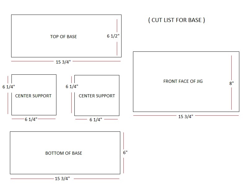
Cut list for Base of Jig :
|
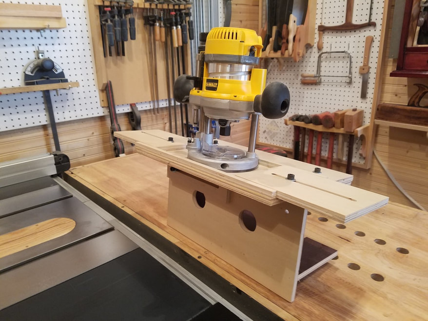
The Jig is constructed from 1/2 inch cabinet grade plywood and is two parts, the base and the adjustable table top. Assembly of the jig starts with the base, the cut list is really easy to follow and is located to the right. Additional hardware needed : * 6 - t-nuts 5/8 * 6 - allen head bolts 5/8 * 6 - washers |
|
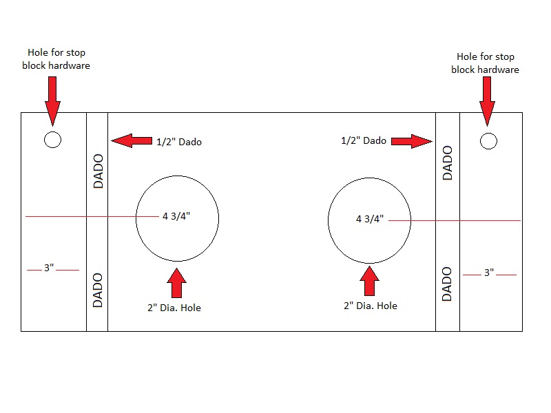
The Face of the Jig
|
The face of the jig requires two dados that measure 1/4 inch in depth and 1/2 inch in width on the back side of the face and at 3 inch in from the edge. These will be to accept the center supports at assembly. * Next two holes measuring 2 inch in diameter need to be drilled at 4 3/4 inch center from edge and 3 1/2 inch from the top, these are for using f-style clamps to secure the work piece. * Last is two holes need to be drilled 1 1/2 inch down from top and 1 1/2 inch in from edge to accept t-nuts for the stop block hardware, the t-nuts can be installed now. Note: When I drilled the holes for the t-nuts I created a counter sink for the nut using a forstner bit drilling just deep enough for the end of the nut to sit flush when installed. |
|
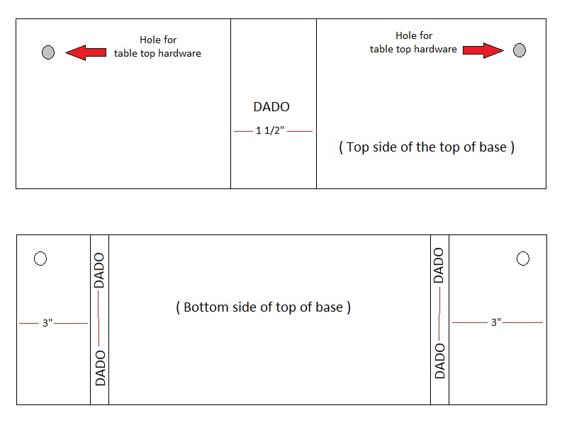
Top of Base
|
In the top side of this piece a dado needs to be cut a 1 1/2 inch in width center of this piece and at a 1/4 inch deep, this is for the guide that will be installed in the table top later in these plans. * Next two holes need to be drilled at 2 inches from both the edge of the side and the edge of the back, to accept the t-nuts for table top hardware, the t-nuts can be installed now. * Last in the bottom side two dados need to be created at 3 inches from the edge measuring 1/2 inch in width and a 1/4 inch in depth to accept the center supports at assembly. Note: When I drilled the holes for the t-nuts I created a counter sink for the nut using a forstner bit drilling just deep enough for the end of the nut to sit flush when installed. |
|
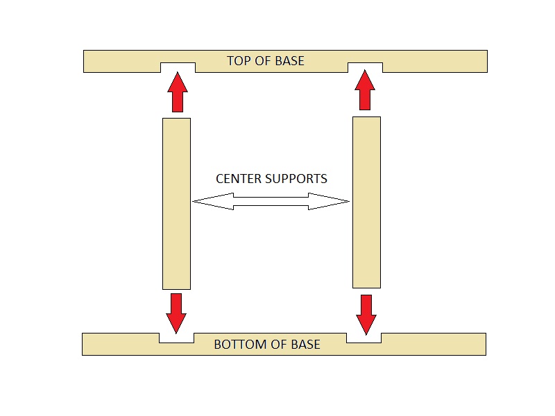
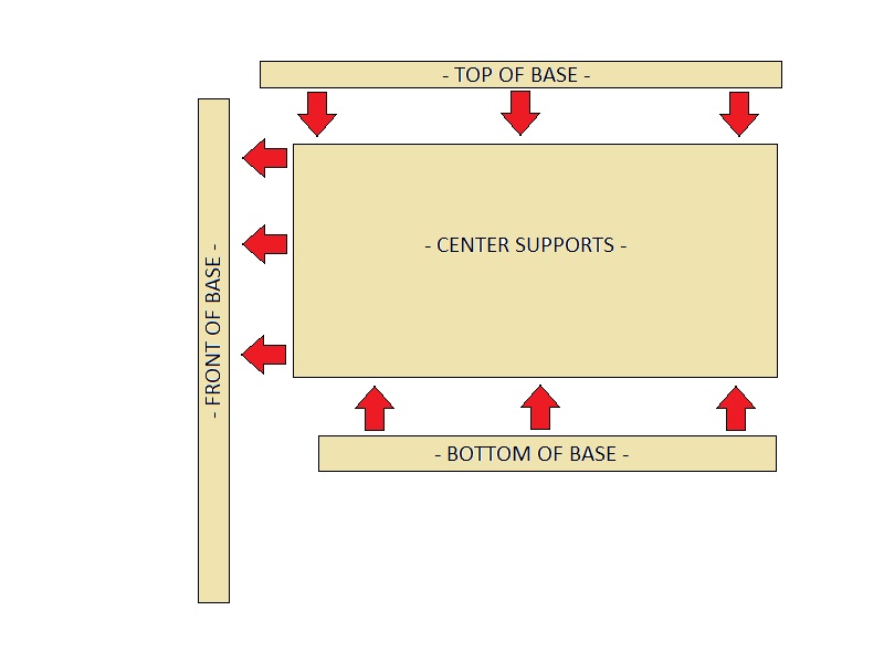
Assembly of the Base
Assembly of this jig is really simple, after applying glue to all dados then install center support, first into top of base then attach front of base keeping in mind that the top of the base should be flush with the front edge of the front of the base, then install into bottom of the base. After base is clamped together use a square and ensure that the base is square.
|
|
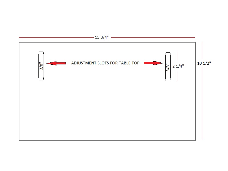
The Table Top
|
First cut the table to size 15 3/4" x 10 1/2" * Two slots approximately 2 1/4 inch in length and 3/8 inch wide need to be created to the back side of the table. 2 inch in from the edge of the side and starting at 2 inch from the back edge of table, these are for adjusting the table top. |
|
|
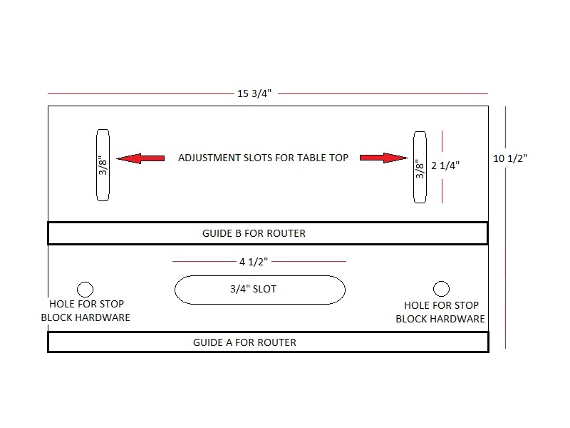
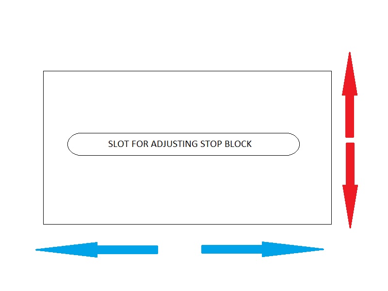
The guides for the router referred to as guide A and guide B in the image to the right, are created from a piece of 1/2 inch plywood cut to a 1/2 inch square. The distance between them will be determined by the width of the base of your router. The router should fit snuggly between guide A and guide B when slid from left to right. Both guides are glued down then pin nailed in place. * Next the location for the two holes to mount the t-nuts for the stop blocks and the slot the router bit will create the mortise through. These holes will be center between guide A and guide B. The holes for the stop block hardware should be 1 inch in from the edge of the sides. The slot I created is 4 1/2 inches long by 3/4 of a inch wide and seems to work great at this size, but can be changed to suit your needs. * On the bottom of the table top a runner measuring 1 1/2 inch wide by a 1/4 of a inch tall and 7 inches long is attached with glue and screws that are counter sunk. The runner is attached center of bottom and runs from just behind slot to the back of the table. |
|
|
The width of the stop blocks for the table top will be determined by the distance between guide A and guide B ( indicated by the red arrows in illustration to the right ) the stop blocks should fit snuggly between the guides but move smoothly. The blue arrows indicate the length of the stop blocks, this distance is measured from the center of the table top out to the left or right edge as shown in the video above there are two, one for the left stop and one for the right stop. This same stop block is used for the stop on the front face of the jig and measures 8 1/2 inches by 3 inches. |
|
Over view of assembled jig
|
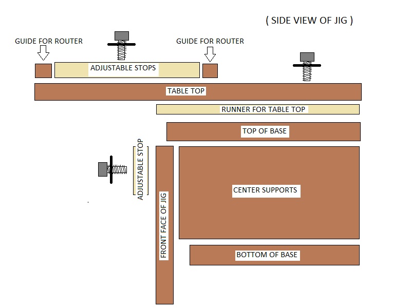
A over view of the jigs assembly is pictured to the right. Foot notes - * When making the slots for the adjustable stops and the table top I used my router table and this step can be viewed in the build video for this jig. * I used allen head bolts for this jig because I was concerned that knobs may interfere with the movement of the router specifically when used for the stop blocks in the table top. |
|